Understanding the Welding Failure in Ball Grid Array (BGA) Head-in-Pillow


Imagine installing a new smart air conditioning controller in your home. It's a sunny day and you want to set your weather, but... suddenly the screen starts flashing and stops showing the image, which makes you unable to set it up… what a mess!
When the diagnostic technician receives the controller, he finds that the electric card fails in the functional test, but in visual inspection, no defect in the welding is detected. This case could be a “head-in-pillow” BGA failure case.
This article will answer the following questions to better understand such condition in welding.
What is head-in-pillow all about?
What are the causes of such failure? How do we prevent and detect it?
What is the head-on- pillow and what effects does it have?
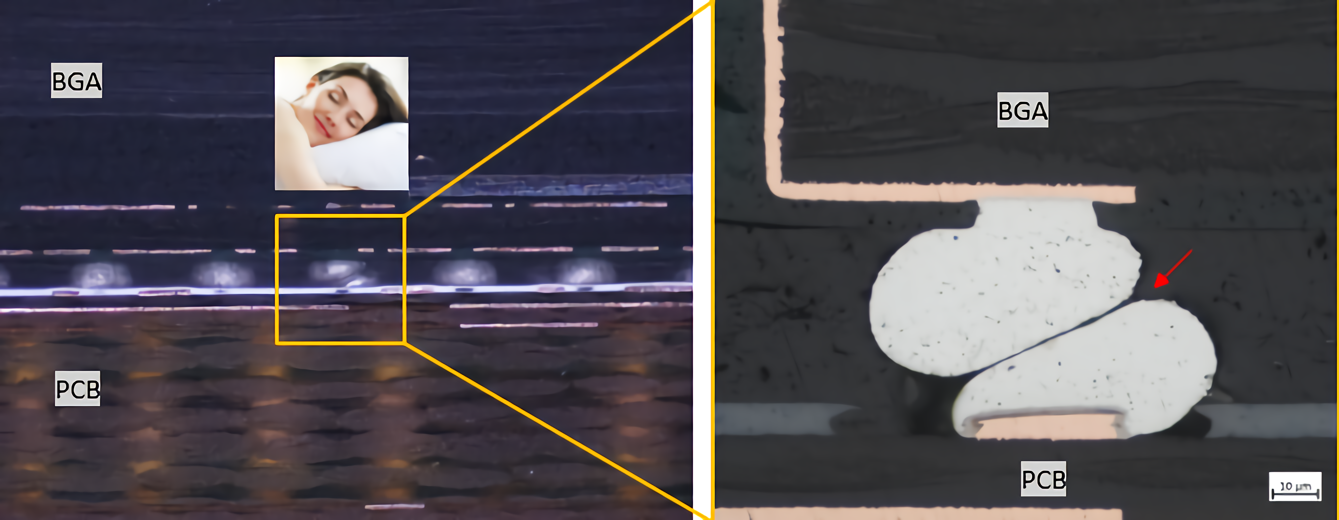
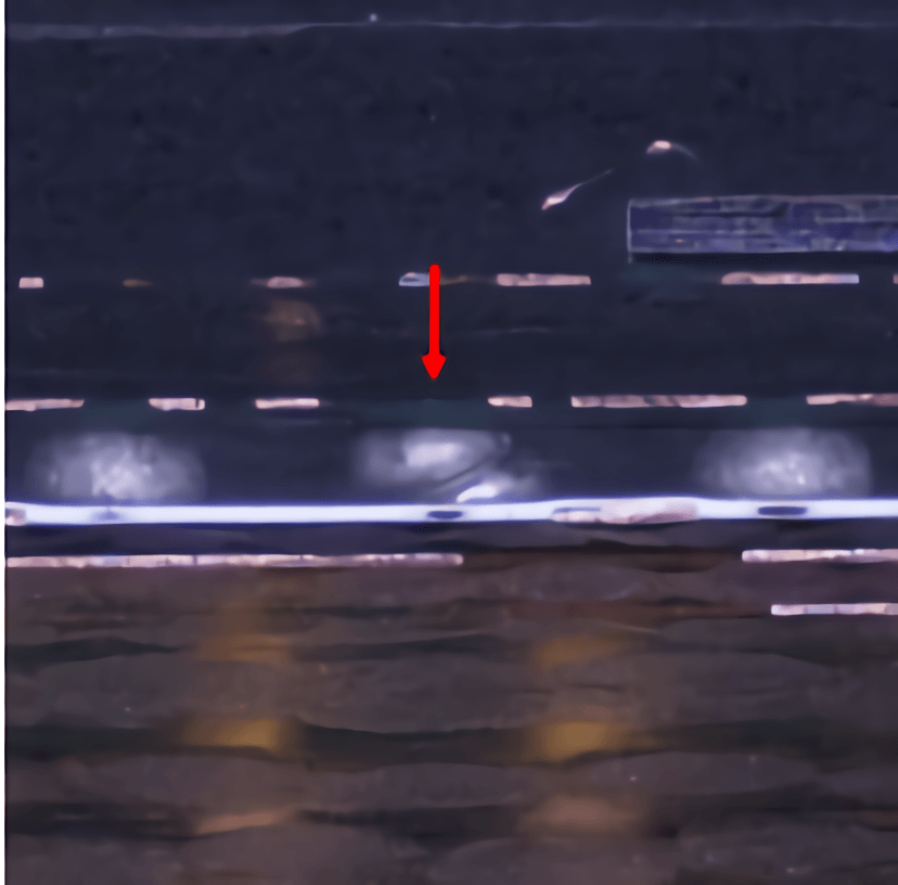
Figure 1 - Stereoscopic Microscope at 50x Figure 2 - Metallographic Microscope at 500x
It is called head-in-pillow as shown on the image as it involves the welding sphere of the BGA along with the paste of the PCB. This may require a little imagination. To clearly visualize such condition, a sectional cut of the PCBA can be made as shown in figure 1.
This condition in welding causes failures due to little or no welding joint, that is, it can occur during production or in the field. At figure 2 there is a complete separation of the welding spheres although it can also present a poor fusion, which results to a latent failure.
What causes such occurrence?
It happens when the PCB paste and the BGA weight do not bind during the reflux furnace process as illustrated in figure 3.
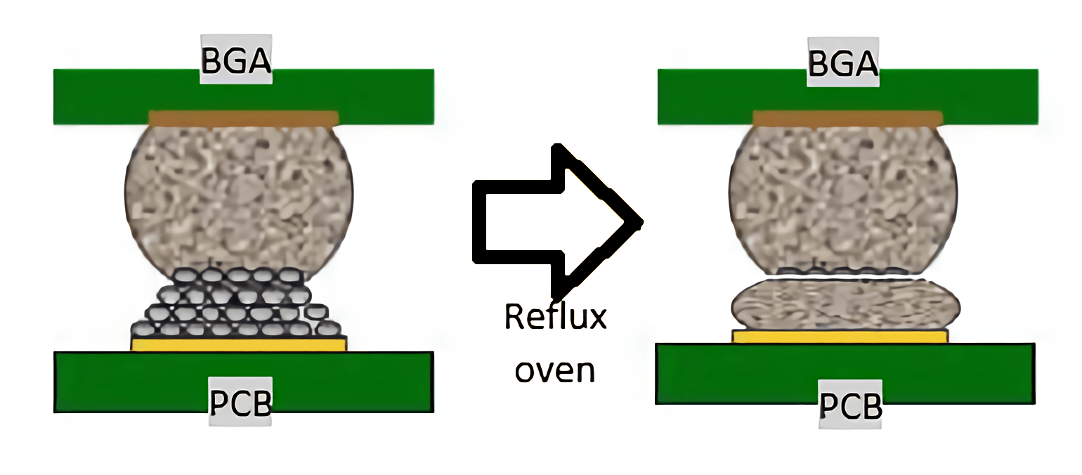 Figure 3 – Illustration of the BGA and PCB before and after the reflux oven.
How does IMI MX prevent and detect such failure?
To detect this welding condition, an X-ray inspection is done at an angle between 55° to 75°.
as shown in the following series of Figures 4 to 6.
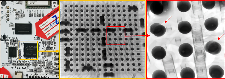
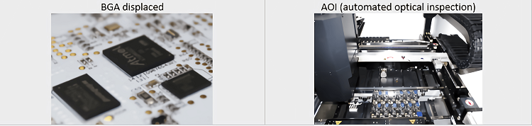
Figure 4 – Visual inspection of the PCB.
Figure 5 – X-ray inspection of the BGA with the "head-in-pillow."
Figure 6 – Close-up of the spheres of the BGAs with the bad spheres identified.
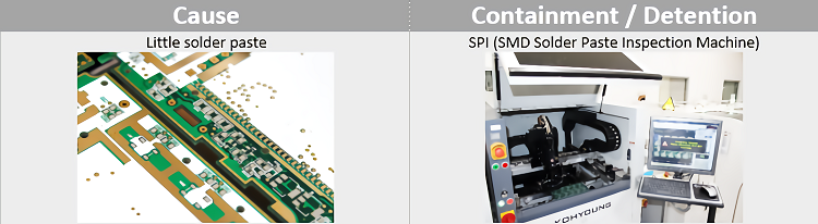
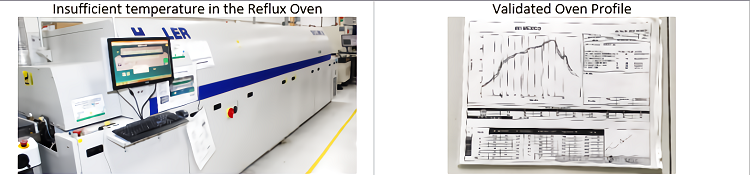
In the following table you will find some probable causes and how we ensure containment and detention.
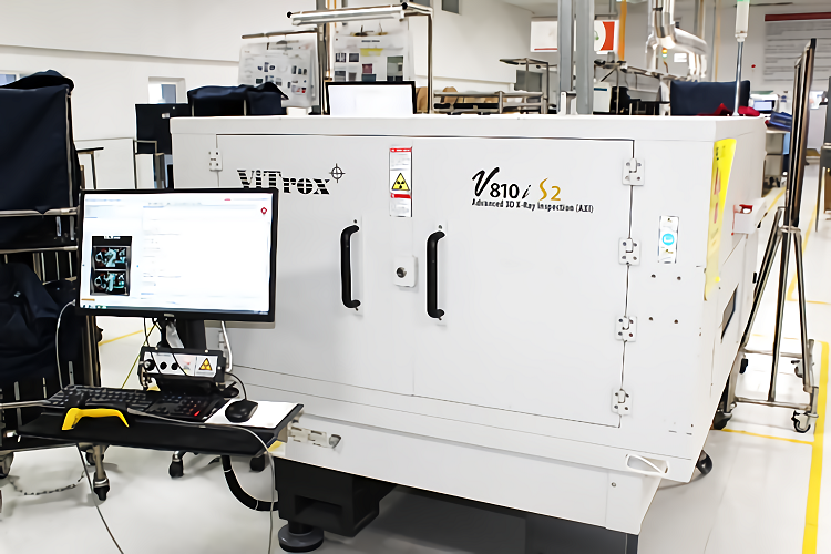
If failure occurs despite the measures undertaken, we have an advanced 3D X-ray inspection system for a more advanced detection system.
Now you have a bit more knowledge about the "head-in-pillow" enabling you to detect it and solve it.
Other White Papers
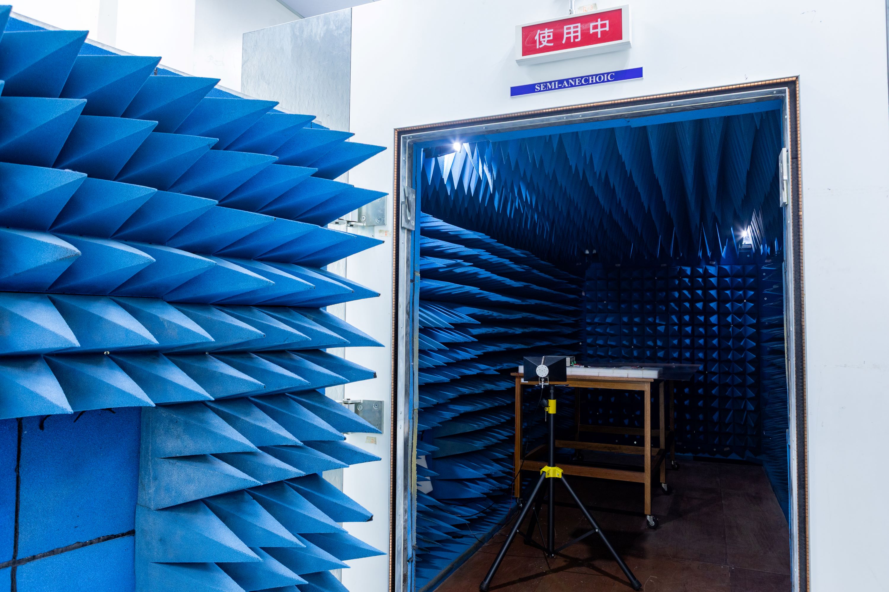
Unlocking Compact EMC Compliance: How IMI’s 3m × 3m × 5m Semi-Anechoic Chamber Enables Full 3-Meter Radiated Emission Testing