Unlocking Compact EMC Compliance: How IMI’s 3m × 3m × 5m Semi-Anechoic Chamber Enables Full 3-Meter Radiated Emission Testing
By: Gilbert A. Diwa, Ph.D. Photoscience, MS Physics, BSCS
Principal Engineer, Analytical Testing and Calibration (ATC) Laboratory
Integrated Micro-Electronics, Inc. (IMI)
Abstract
As electronic products become smaller, faster, and more complex, achieving regulatory electromagnetic compliance (EMC) has never been more challenging. Traditionally, 3-meter radiated emission (RE) measurements require large, costly 10m × 10m × 10m chambers.
IMI’s Analytical Testing and Calibration (ATC) team has proven that a 3-meter RE test can be successfully executed inside a compact 3m × 3m × 5m semi-anechoic chamber, without compromising data quality or compliance integrity.
This breakthrough offers our customers:
- Cost-efficient EMC pre-compliance and testing
- Faster product qualification cycles
- Accessible, scalable EMC testing for early-stage designs
- Reliable results aligned with FCC Part 15 Class B and CISPR 32 standards
The company’s method—elevating both the DUT and antenna to 1.4 m and optimizing the chamber environment—unravels a new level of flexibility in EMC validation for modern electronics.
Introduction
Commercial electronics and electrical devices are tested based on CISPR 32 and FCC standards. The Semi-anechoic chamber housed in ATC attempted to conduct a 3m radiated emission test using biconical antenna (BA). The test range is from 30 MHz to 960 MHz using FCC Part 15 – Class B (3m) Frequency Limits.
Theory
High speed switching in typical electronic devices nowadays are expected to emit electromagnetic interference (EMI) following Maxwell’s classical electrodynamic equations.

Fig. 1. Antenna at the right side of the drawing captures the electromagnetic interference coming from the DUT. The dashed line indicates the radiated electromagnetic fields from the DUT.
The BA is oriented horizontally to trap the horizontal polarization of the electric field lines.
Experiment
The illustration in Fig. 2 shows that the DUT is 3.0 m away from the BA to satisfy the requirements. The DUT and BA are of the same height to trap the radiation emanating from the DUT. The PS line is connected to the LISN before connecting to the DUT to ensure filtered power. The PS and SA are installed outside the semi-anechoic chamber to minimize the noise detected by the BA. Note that the triangular radio wave absorber eliminates the reflected electromagnetic signal.
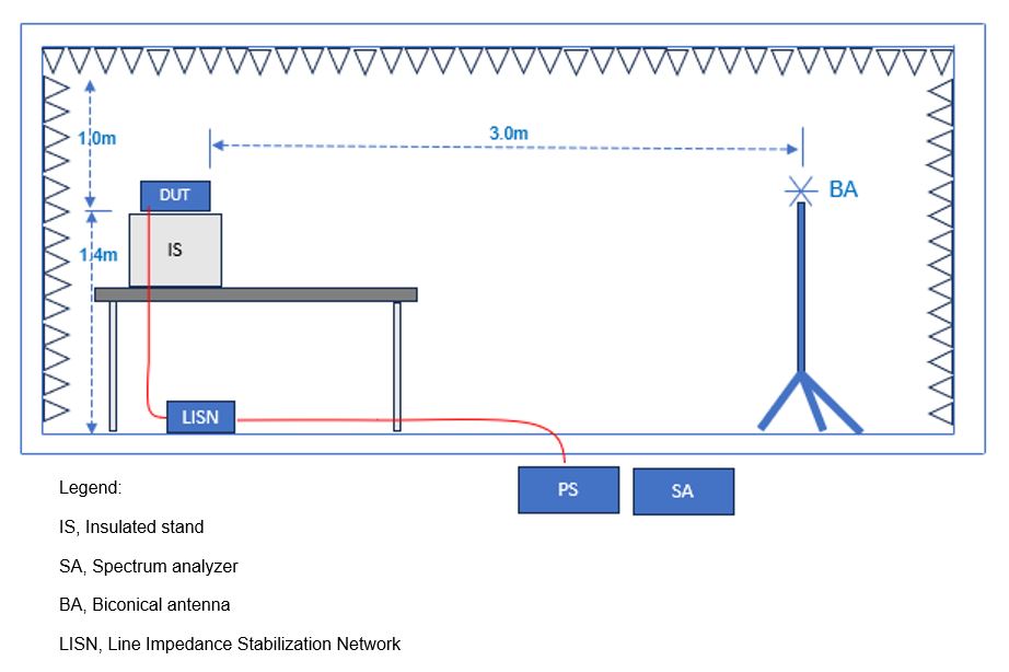 Fig. 2. The DUT is elevated 1.4m with respect to the ground in line with the BA. The distance between the DUT and the BA is 3m.
List of accessories used to facilitate the radiated emission test.
- Spectrum Analyzer 9 kHz to 6.2 GHz
- Biconical Antenna 30 MHz to 1000 MHz
- Line Impedance Stabilization Network (LISN) 5 uH
- Semi-Anechoic Chamber 3m x 3m x 5m with shield performance of -80 dB (30 MHz to 1 GHz) and -60 dB (1 GHz to 18 GHz)
- DC Power Supply
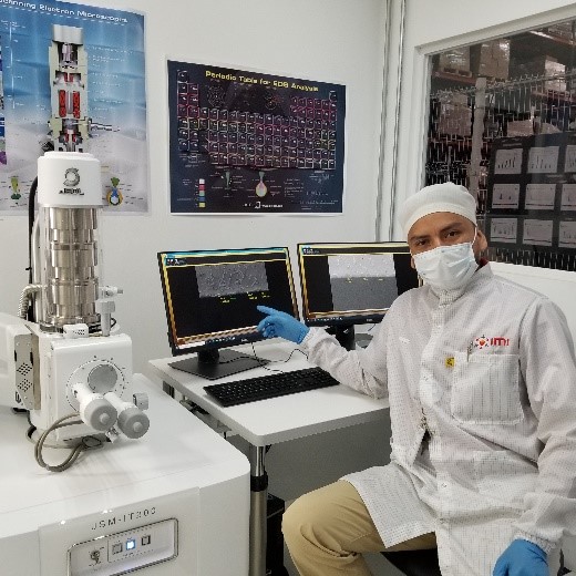
The actual setup inside the semi-anechoic chamber is shown in Fig. 3. The side wall and the ceiling are covered with 500mm x 500mm x 400mm high radio wave absorber made up of urethane. The IS is a box used to hold the DUT at a higher position. A higher position for the DUT is necessary to maximize the signal absorption by the the copper cladded table to prevent signal reflection.
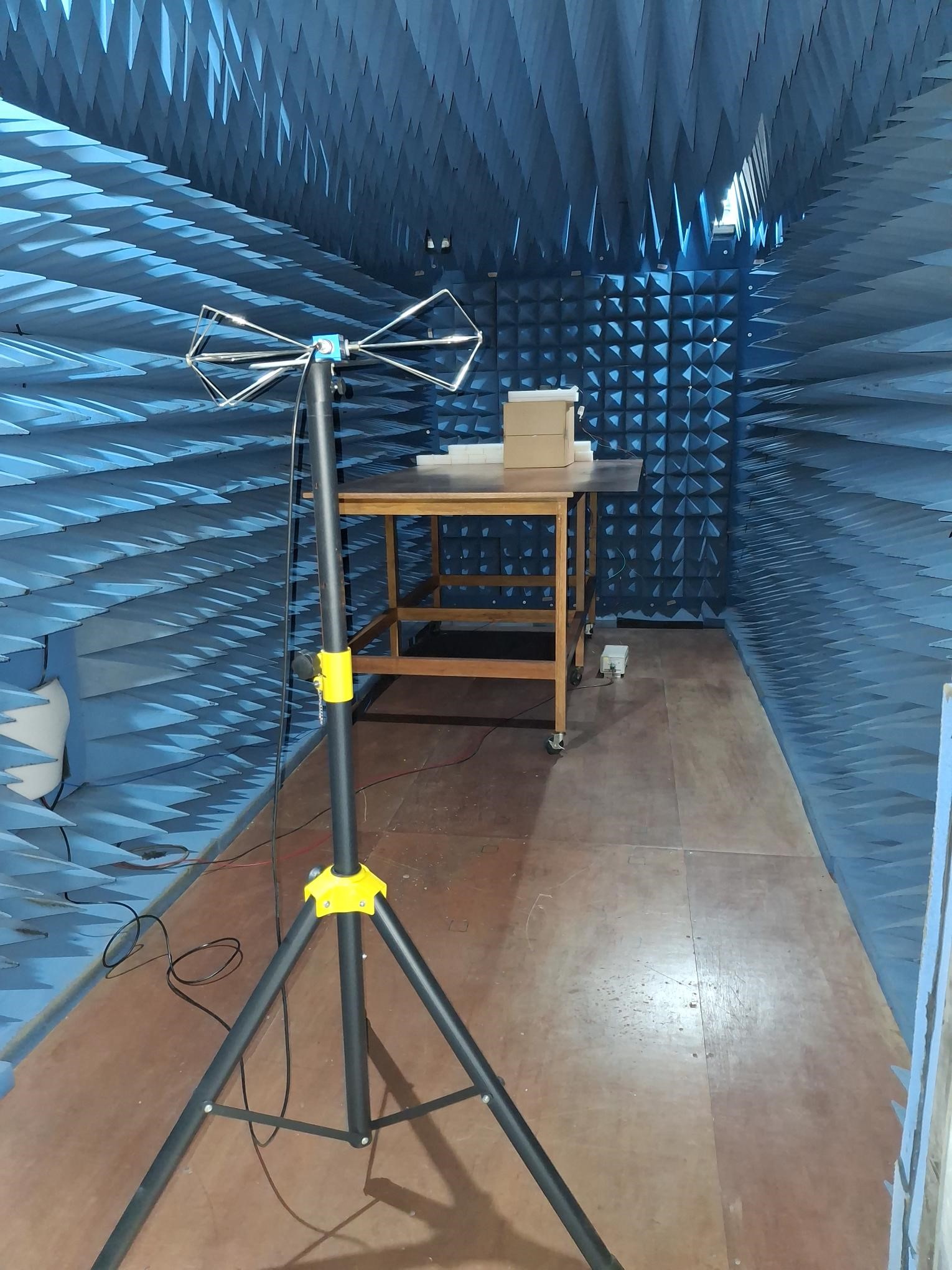 Fig. 3. Set-up of the 3m Radiated Emission inside the Semi-anechoic chamber.
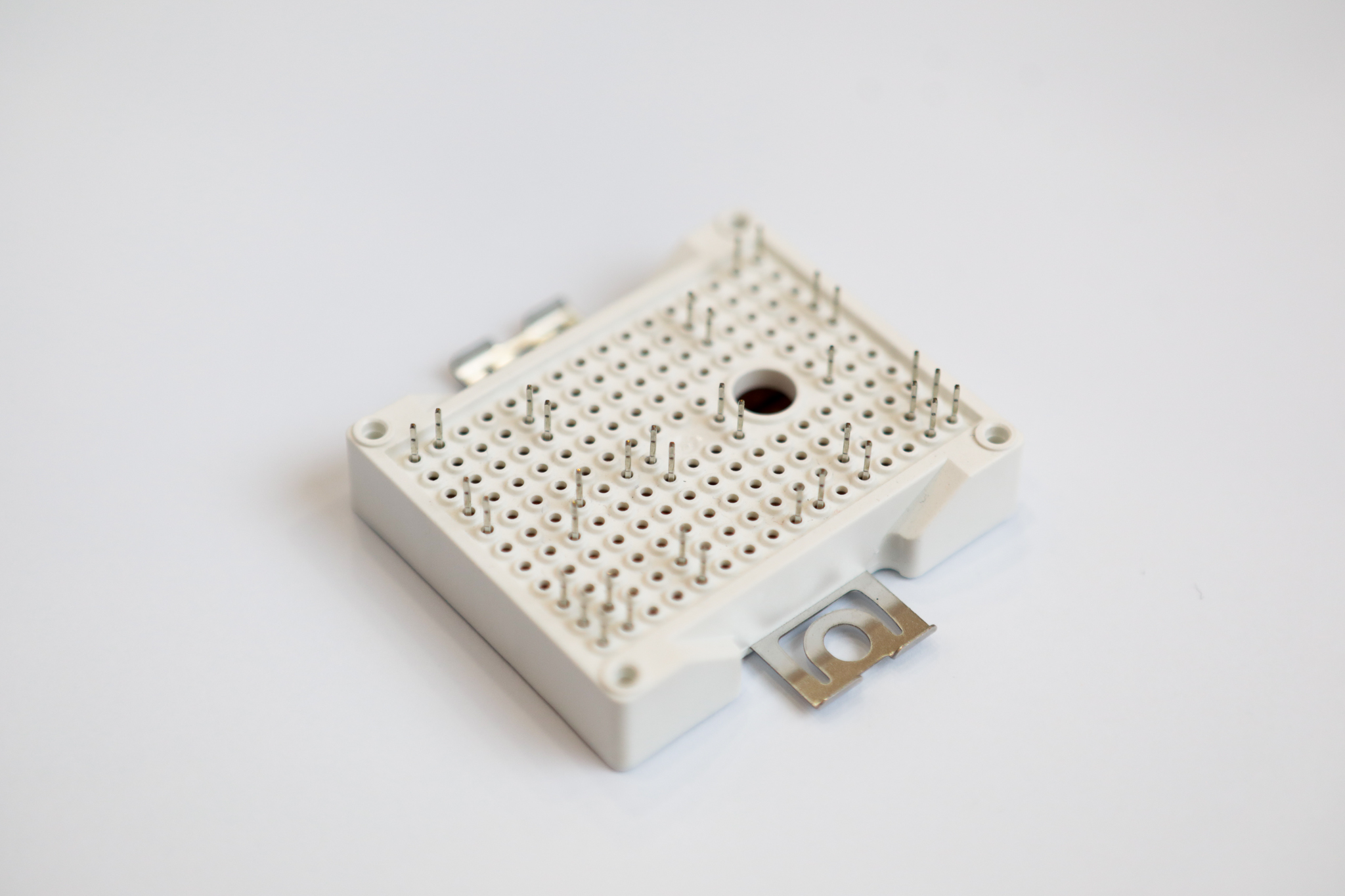
A closer shot of the DUT is taken to show its relative position on the copper cladded table.
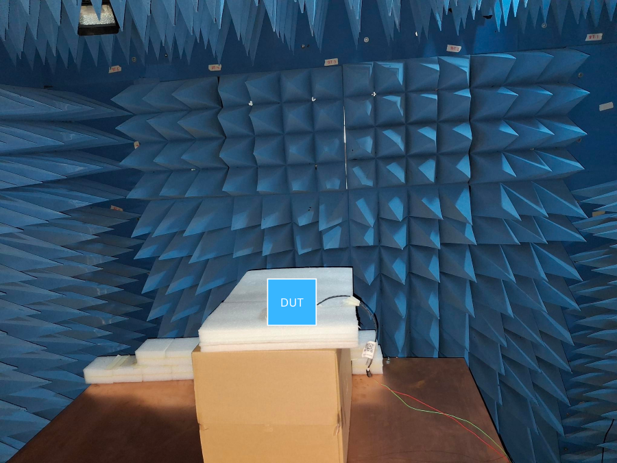
Fig. 4. DUT on the insulated stage. The height of the DUT from the ground is 1.4m.
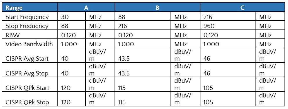
USS-FCC Part 15 – Class B (3M) Frequency Limits was adopted as shown in Table 1 that ranges from 30 MHz to 960 MHz. CISPR QPk and CISPR Avg are the data selected for detection in the units of dBuV/m.
Table 1. US-FCC Part 15 – Class B (3m) Frequency Limits
 Results and Discussion
Initially, neutral line is tested to determine the baseline. Neutral line describes a complete circuit without supplied power.
The baseline is about 28 dBuV/m for the CISPR Avg and about 35 dBuV/m for CISPR QPk.
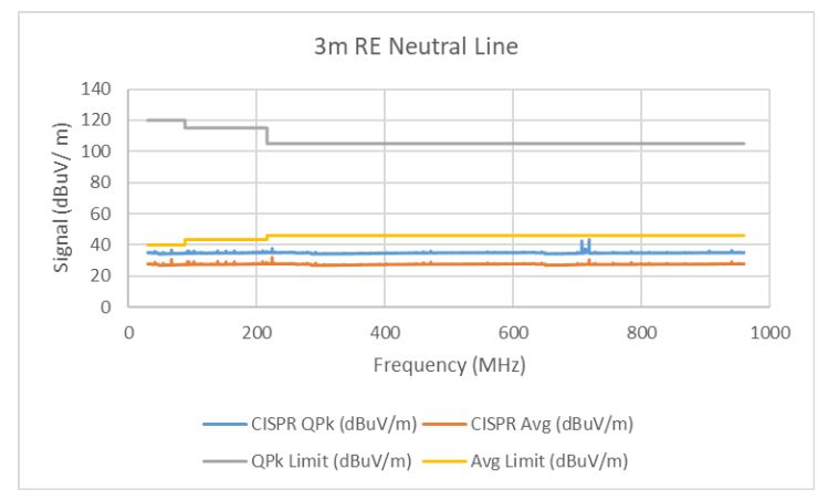
Fig. 5. Neutral Line 30 MHz to 960 MHz horizontal polarization data.
Frequency peaks detected are below the CISPR QPk and CISPR Avg limits.
Table 2. Limit Tests. The Neutral Line tested peaks are lower than the limits.
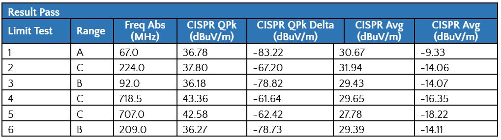
The Live Line indicates that the power is supplied to the DUT without load. The CISPR QPk and CISPR Avg data for the Live Line and Neutral Line are almost similar.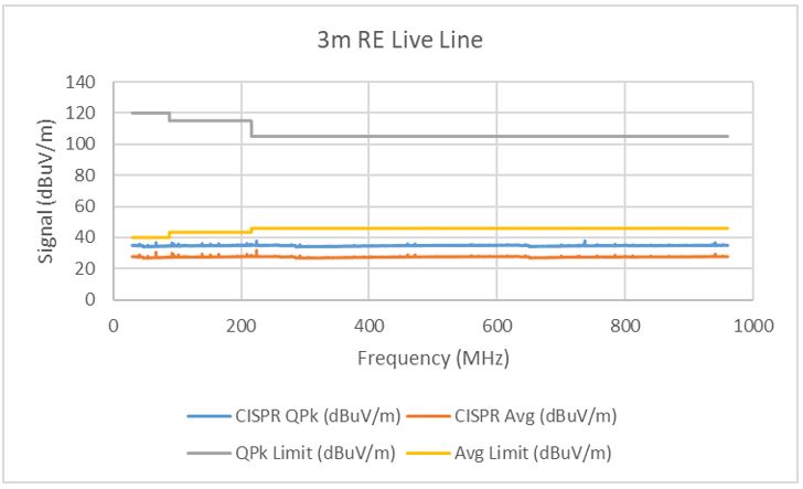
Fig. 6. Live Line 12 V, 0.5 A, 30 MHz to 960 MHz horizontal polarization data.
Frequency peaks detected shown in Table 3 shows that they did not surpass the limits.
Table 3. Limit Tests. The Live Line tested peaks are lower than the limits.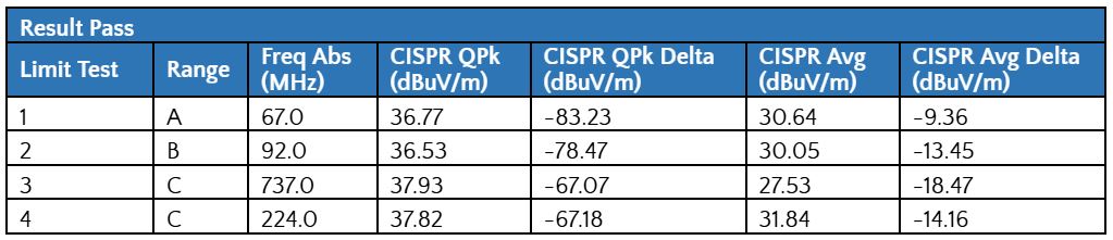
Conclusion and Recommendation
The test demonstrates the capability of the 3m x 3m x 5m Semi-anechoic chamber to execute a 3m radiated emission test. The SAC was able to filter out external electromagnetic signals as indicated by the Live Line and Neutral Line plots.